I wrote previously about Lombardi's efforts to open up Blueprint using XPDL 2.1. A BPMN diagram created in Blueprint can be exported as XPDL and imported into itp commerce Process Modeler for Visio, the tool I use in my BPMessentials training. This is great! Even though it is a standard, BPMN is rarely portable between tools, something that baffles users. But I noticed the lanes did not import properly. My investigation into why has increased my understanding of the portability problem.
A long time ago, when we wasted time talking about the relative merits of BPEL vs XPDL, Keith Swenson used to go on and on about the need to port the diagram graphics in addition to the semantic model. (BPEL has no graphics model, but today that seems almost besides the point.) I argued at the time that graphics portability was hopeless anyway, since each tool uses different graphics libraries, fonts, connection points, etc. You could never get the graphics to port exactly and remain editable.
The truth, as it turns out, is something in between. Portable BPMN graphics is really an approximation of the layout, capturing the arrangement of nodes in swimlanes and connector bendpoints, but not necessarily fonts, precise connection points, etc. Those are still determined by each tool. This is more or less in line with user expectations, and XPDL can deliver on this... in principle.
Upon further investigation of the Blueprint-ITP issue, I found out that ITP ignores the graphics info in the Blueprint XPDL and reconstructs the diagram from the semantic model (sans lanes). The engineer said it was too complicated to explain, as he headed off for vacation. So I had to figure it out on my own.
Turns out there are several related issues. One is coordinate systems. "Standard" XPDL measures node xy coordinates as position of the top left corner relative to the top left corner of the page. Yes, XPDL expects diagrams to have pages, but they are not required. Blueprint has no pages.
Second is scale. There is a PixelsPerMillimeter scale attribute in XPDL, but tools can omit or ignore it. Scale turns out to be important because most of the graphics in the diagram are fixed in size.
Third is standardization in XPDL. The spec says, per Robert Shapiro, my XPDL guru:
X and Y coordinates of node's upper left corner (bounding box). Tool specific and depends on ToolId. Usual implementation based on upper left corner of page being (0, 0) and all coordinates >= 0.The operative words here are tool-specific and depends on ToolId. You can't have real portability when key elements are tool-specific. It's more like EDI: you can integrate, but it takes side agreements to do so.
In the end, it seems that ITP only imports the graphics when it recognizes its own ToolId. OK, I can forge that. And it measures coordinates of node centers relative to bottom left corner of page. OK, I can do the math. And it uses the PageId attribute. That's a bit harder, since Blueprint is pageless. When it constructs the graphics from the imported Blueprint XPDL, ITP creates pages for the expanded subprocesses. This is the hierarchical style I teach in BPMessentials. I'll figure that out somehow...
I set about writing an XSLT transform that would map the Blueprint export XPDL into something ITP can import, including graphics. I played around to arrive at a scale factor that made the imports look OK. If I had more time, maybe I could figure out how to create multi-page hierarchical models in the XSLT, but to start I just put everything in one page -- which is what the Blueprint export actually provides.
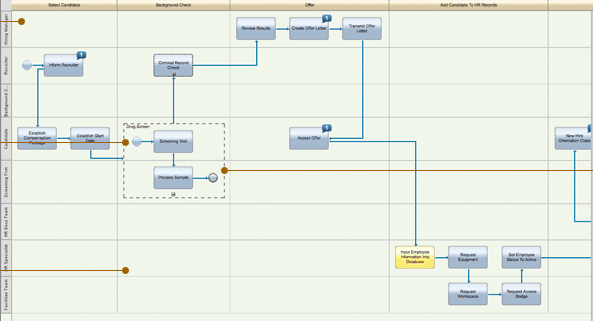
Here are the results. This is a fragment of the sample Hiring process on the Blueprint site:
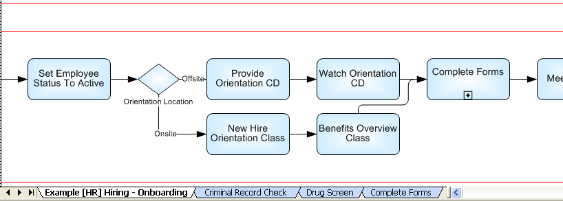
Here is how it looks imported from the raw XPDL. Note the lanes have been lost and pages for the subprocesses have been added.
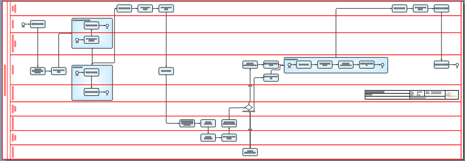
Here is the import after my XSLT transformation:
The lanes are back! Actually, I had to do two things first in Visio. Send the expanded subprocess shapes to the back layer in order to see the connectors, and change the page size (fixed at A4 in the XSLT) to fit the drawing. Note the connectors do not touch the activities in exactly the same place as in the Blueprint original, but the general layout is preserved.
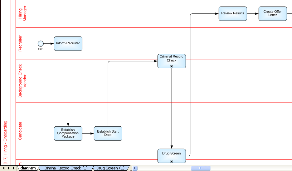
And here's a cool thing you can do in the ITP tool: convert the expanded-inline subprocesses into collapsed subprocesses with the expansion on another page of the diagram, as in the hierarchical style. Here is what that looks like:
I'm not much of a programmer, but it seems to work. If you are interested in the xslt, you can download it here. I used the xsl:function tag, so it requires an XSLT 2.0 engine, such as XMLSpy (the engine is free from Altova). It probably could be rewritten in XSLT 1.0 without that.


