In my DMN 1.2 Wishlist post, one of the key items is the ability to represent a single decision node having complex decision logic with a “sub-DRD” equivalent to the boxed context representation allowed under DMN 1.1. In his comment, James Taylor sighs loudly and adds that if I understood the spec better I would realize that what I want can be done already in DMN 1.1. I don’t see that, but a picture here is worth 1000 words.
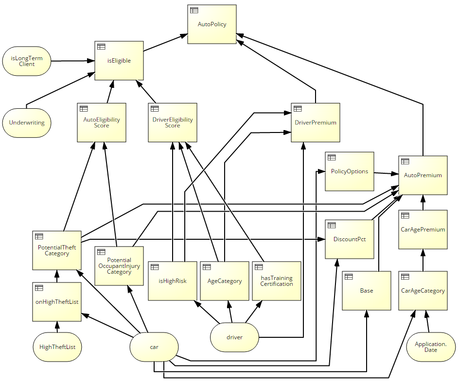
Here is a DRD of the UServ auto insurance example taken from Chapter 14 of my DMN Method and Style book and slightly modified. It has only 20 decision nodes – far less than Larry Goldberg’s manageability limit of 30, but still a bit hard to take in with its mess of crossing lines.
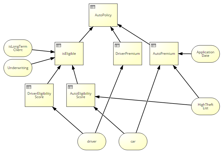
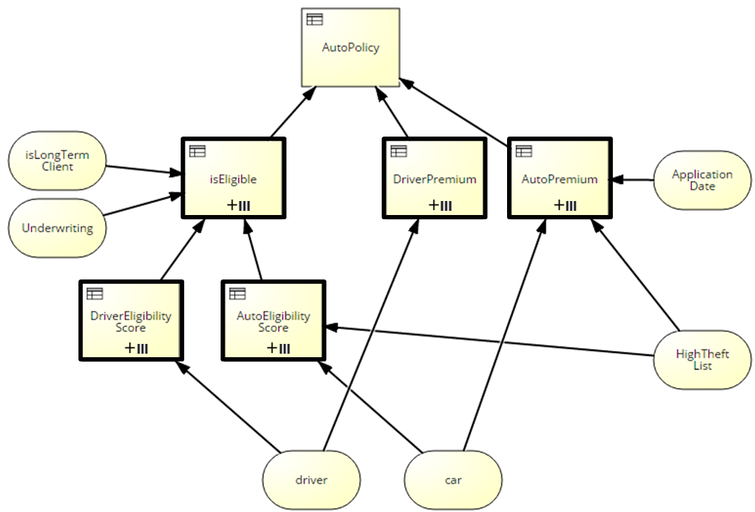
Here is a simpler high-level view of the same business decision, much easier to understand and probably how I would begin to decompose the logic in top-down fashion:
What I want is that this simpler DRD, adorned with suitable symbols and border styles, is a valid representation of the same end-to-end decision logic described in the detailed DRD. James says this is already possible under DMN 1.1, it’s just a tooling issue. But is it?
The simpler DRD has 6 decision nodes, here colored green in the detailed DRD:
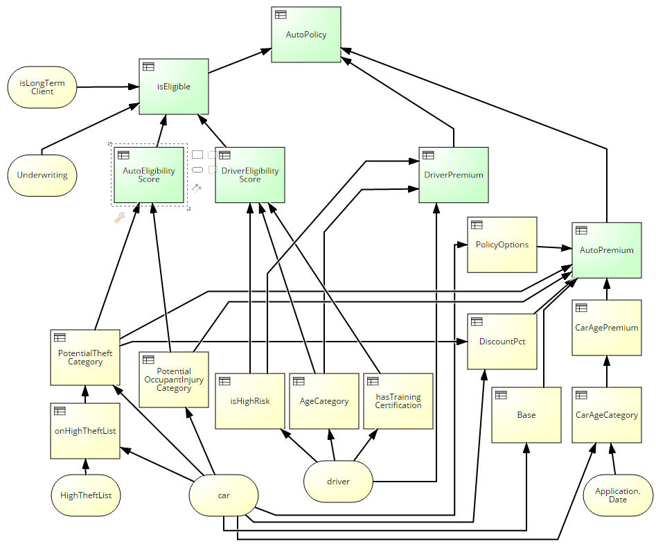
In the high-level DRD, for example, the decision logic of AutoEligibility Score depends only on the variables car and HighTheftList, both input data elements. But in the detailed DRD, it depends on the variables PotentialTheft Category and PotentialOccupantInjury Category, both decisions and not the same thing at all. Unless you say, “Well, of course, the decision logic of the node has to change if you change the DRD representation,” I don’t see how the diagrams are equivalent under DMN 1.1. To make them equivalent, you need to encapsulate the supporting decisions of AutoEligiblity Score inside that single decision node. And you can do that today already with a context, a boxed expression that using FEEL looks like this:
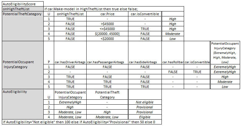
This context is equivalent to the tree of supporting decisions of AutoEligibility Score in the detailed DRD, and it is true that if you make this context the decision logic of that node in the high-level DRD, the high-level and detailed logic for this decision are the same. The problem with boxed context is that almost no tools support it, saying that business users won’t like it. Maybe that is the case, maybe not, but what is clear is that there is a “sub-DRD” representation of this context (and those of the other decision nodes in the high-level DRD) that makes the high-level DRD exactly equivalent to the detailed DRD, but much easier to visually understand. My proposal is that the sub-DRD is displayed as a separate diagram hyperlinked to the decision node in the high-level DRD, much like a child-level BPMN diagram is hyperlinked to a subprocess in the parent-level diagram.
This sub-DRD notion is related to other items on my wishlist as well. Actually, the diagrams above only work for an insurance policy with one driver and one car. The UServ scenario specified multiple cars and multiple drivers on a single policy. You can do this in DMN 1.1 today, but to iterate a decision requires a BKM and a for..in..return expression. Thus in addition to (not instead of) the decision nodes you need to draw BKM nodes, with their own arrow connectors – more clutter – and if you think the boxed context above is not business-friendly, you’re really going to hate for..in.return.
The wishlist proposals say instead of drawing the BKMs in the main diagram, use a thick border on the decision node to indicate a “call” to a reusable function, i.e., BKM. In the tool, such a node would typically be hyperlinked to diagrams representing the parameter mapping and the BKM logic. And the 3-bar symbol indicates that the called function is “multi-instance,” iterated over a repeating input element. (Here the input data elements car and driver are tables, one row per car or driver.) In the wishlist post, such a multi-instance decision was shown expanded, as it is currently implemented in Signavio. In the diagram above, it is shown collapsed.

Bruce
Why would you show it as a single diagram? What possible value would that add and what in the spec makes you think you need to do this? You could draw multiple diagrams now and have different subsets of the nodes on each one. By only drawing the one complicated diagram you overstate your case as you well know. The spec allows you to draw multiple diagrams, each showing a different perspective. A high level diagram can be combined with multiple more detailed ones. And furthermore can be done more flexibly as I can build them specifically for different audiences, showing one audience a different mix of detail than another.
The only thing you want that is not in the current spec is the ability to show indirect information requirements – showing that a decision ultimately depends on a piece of data that it does not directly depend on. Why not just ask for that? I am not sure its that useful and it is potentially confusing but it would be a lot easier to add to the notation.
I must not be explaining it well. When you ask why show the end-to-end logic as a single diagram, I assume you mean you could draw a diagram of, say, AutoEligibility Score, and another one of DriverEligibility Score, etc. I agree you can do that to create a flat model chopped up into little pieces. And maybe you even stub out the other pieces to acknowledge they exist. In BPMN that’s like using Link events as off-page connectors. I personally think that’s bad practice but it is allowed and some people do it.
I know you say that what is in the DRDs doesn’t matter, what matters is the model captured in a repository. OK that is your view. The Method and Style philosophy, which has been very successful in BPMN and which I am now applying to DMN, is that the only thing that counts is what is in the diagrams (DRD and boxed expressions). So if one diagram just omits another part of the decision model, or shows a stubbed out decision (absent its information requirements and supporting decisions), for me it is not properly representing the end-to-end decision logic. I think the end-to-end decision logic should be represented by a single decision model (definitions element) which is rendered visually as a single DRD. So the value of the sub-DRD is that it allows such a DRD to be constructed hierarchically without hiding anything or using unspecified filtering.
I don’t ask that all modelers adopt my methodology. The sub-DRD idea just makes understanding the end-to-end model easier. There is also a methodological benefit similar to what Alan Fish has put forward for BKMs, as a way to identify major logic elements (or “knowledge areas”) used in top-down decomposition. I just think my approach works better graphically, and does not require the extra step of parameter mapping when reuse is not required.